3 View Drawing
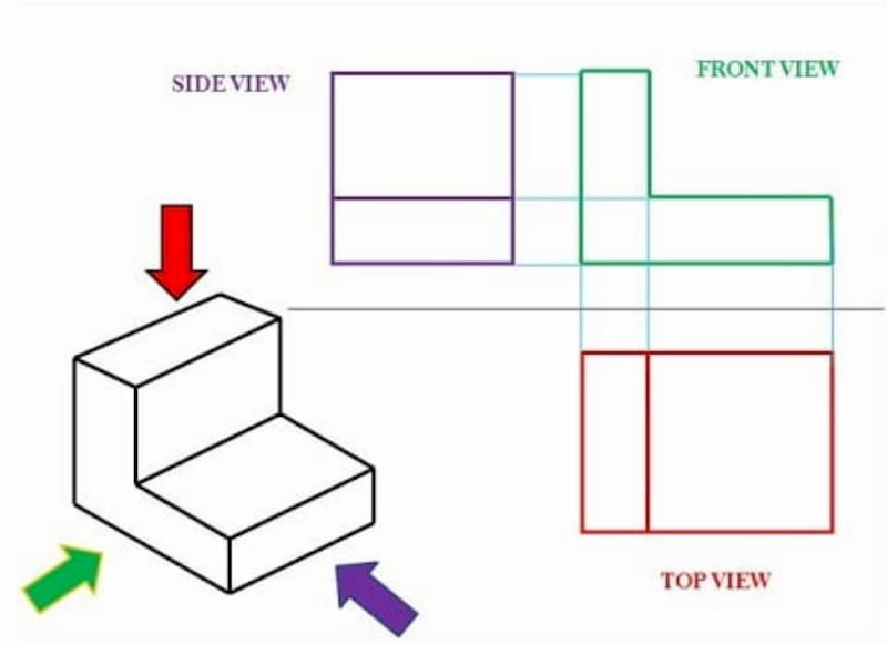
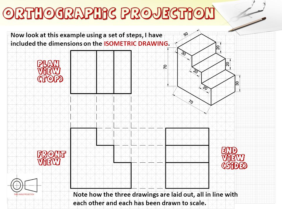
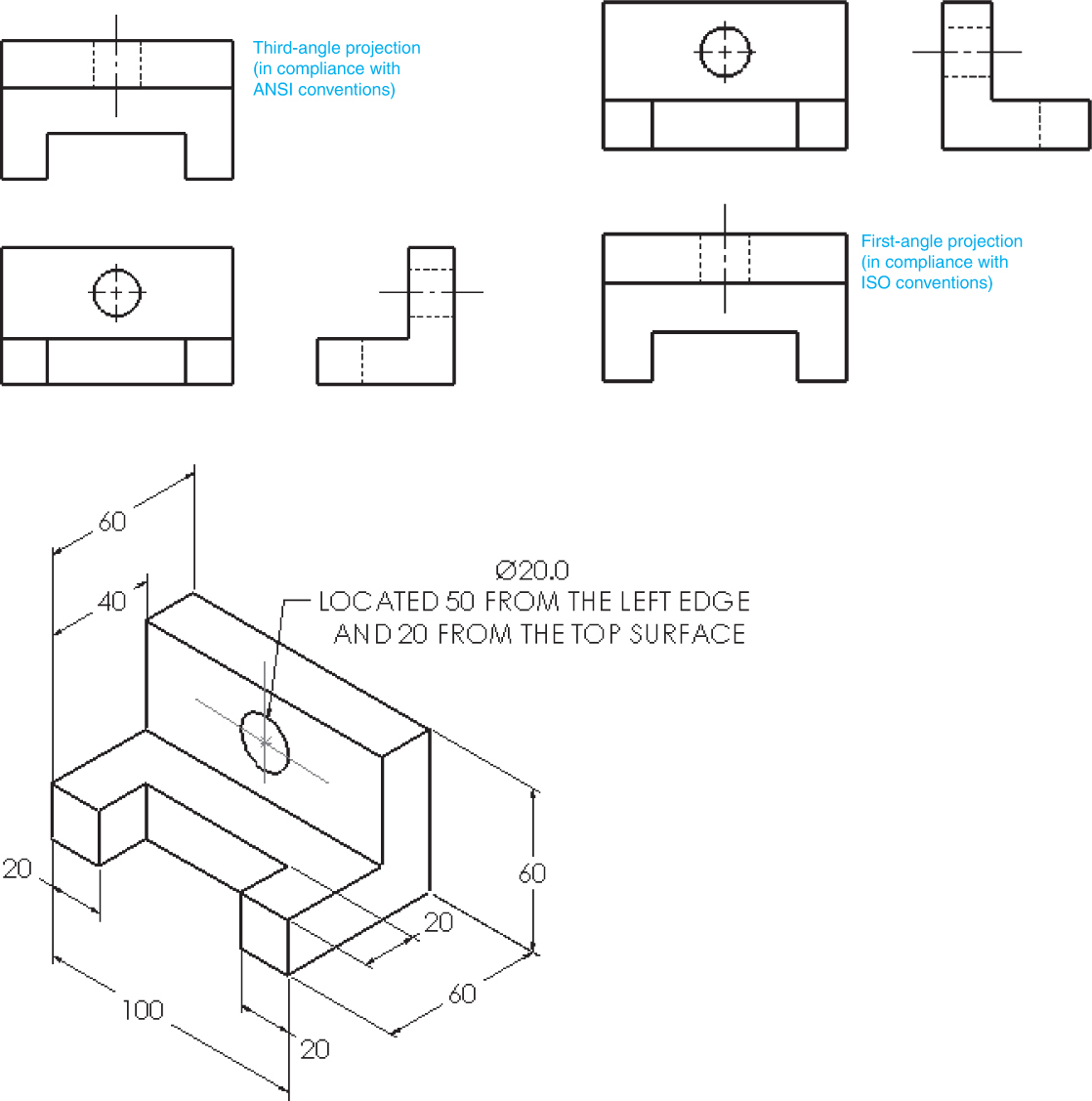
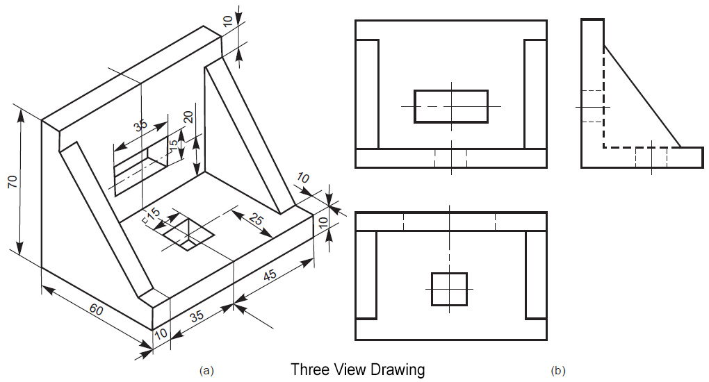
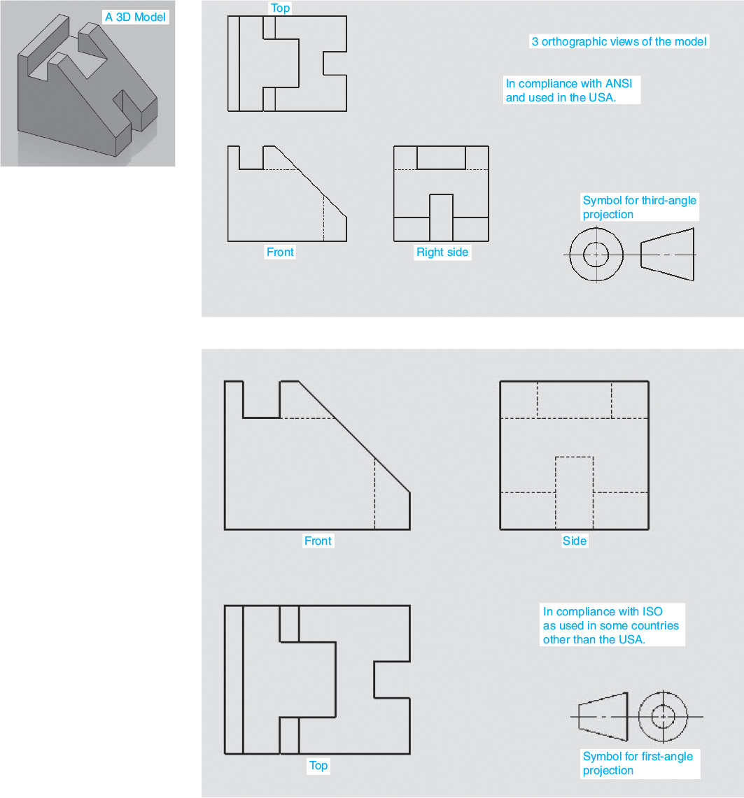
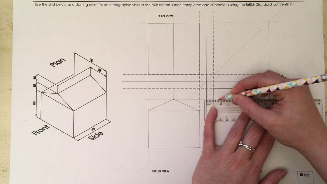
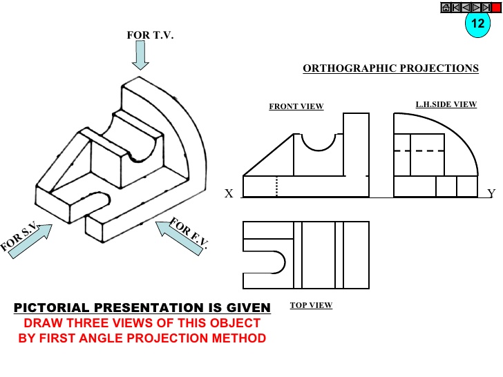
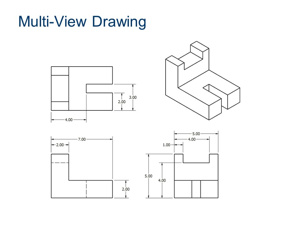
3 View Drawing - Web this is the bread and butter of an engineering drawing. Web orthographic views allow us to represent a 3d object in 2d on a drawing. From the intro to engineering & design curriculum by paxton/patterson colleg. The prevalent form is a continuous line, also referred to as a projection line, which signifies the tangible boundaries of an object. The two main types of views (or “projections”) used in drawings are: Web the orthographic drawing usually includes 3 orthographic views: Web the standard 3 view option under insert > drawing view creates three related default orthographic (front, right, left, top, bottom, and back) views of a part or assembly displayed at the same time. Web a multiview drawing usually consists of three views: Secret service at former president donald trump's rally on saturday took a picture of the gunman and saw him looking through a. I top view r front view right side view using the top view shown in fig. Hidden lines represent features obstructed from view. Web michael harrigan, a retired f.b.i. 2.2 drawing a building in three. Web this is a simple tutorial on how to draw a 3 view orthographic projection drawing in autocad from a given isometric drawing. Web indianapolis police are investigating the death of gavin dasaur, who was caught on video armed and yelling at a driver before being fatally shot in a suspected road rage incident on tuesday. 1 person and shooter dead at least six bangs that sound like gunfire are heard while the republican. With a few simple tricks, you can be drawing like a pro! Web this video explains three view blueprints/drawings and how to determine front views, top views, and right side views. An orthographic view or orthographic projection is a way of representing a 3d object in 2 dimensions. A front view, a top or bottom view, and a left or right view. Although in theory the part could be placed in any orientation, the views are usually chosen to coincide with a natural symmetry of the part—for example, the front, right, and top of the car shown above. Link to purchase booklet of more. 2.1 understanding the horizon line and three vanishing points. Web michael harrigan, a retired f.b.i. An orthographic view. Projection lines project points from the object onto the drawing plane. Web nbc was no. Thus, a 2d view has to convey everything necessary for part production. Web table of contents. The prevalent form is a continuous line, also referred to as a projection line, which signifies the tangible boundaries of an object. The front view, the side view (usually the right side), and the top view. The view orientations used are based on the orientations (front, right, and top) in the part or assembly.the view orientations are fixed and cannot be changed. The collection was compiled from publications dating from the early 1920s but through 2008. 2.1.2 understanding the third vanishing point. How the views are laid out on a drawing depends on whether 3 rd angle or 1 st angle projection is being used. Orthographic views can show us an object viewed from each direction. 2.2 drawing a building in three. Thus, a 2d view has to convey everything necessary for part production. Web the standard 3 view option under insert. The view orientations used are based on the orientations (front, right, and top) in the part or assembly.the view orientations are fixed and cannot be changed. Web a multiview drawing usually consists of three views: Web indianapolis police are investigating the death of gavin dasaur, who was caught on video armed and yelling at a driver before being fatally shot. Web the orthographic drawing usually includes 3 orthographic views: Night 1 of the rnc notably featured donald trump announcing jd vance as his. I top view r front view right side view using the top view shown in fig. Special agent, said the image captured by doug mills, a new york times photographer, seems to show a bullet streaking past. “aboard the rafale” virtual reality “immersive dassault aviation” virtual reality “dassaultair3d” augmented reality “dassault air flight” mobile application “myplanedesign” configurator; Orthographic views can show us an object viewed from each direction. Although in theory the part could be placed in any orientation, the views are usually chosen to coincide with a natural symmetry of the part—for example, the front, right,. The collection was compiled from publications dating from the early 1920s but through 2008. Thus, a 2d view has to convey everything necessary for part production. Orthographic views can show us an object viewed from each direction. Web indianapolis police are investigating the death of gavin dasaur, who was caught on video armed and yelling at a driver before being. 2.2 drawing a building in three. Web the standard 3 view option under insert > drawing view creates three related default orthographic (front, right, left, top, bottom, and back) views of a part or assembly displayed at the same time. Web this is a simple tutorial on how to draw a 3 view orthographic projection drawing in autocad from a. Thus, a 2d view has to convey everything necessary for part production. Follow these steps for each shape. Web orthographic views allow us to represent a 3d object in 2d on a drawing. This kind of representation allows avoiding any kind of distortion of lengths. 2 with about 2.3 million, followed by abc (2 million), cbs (1.6 million), cnn (968,000). The two main types of views (or “projections”) used in drawings are: 2 with about 2.3 million, followed by abc (2 million), cbs (1.6 million), cnn (968,000) and msnbc (798,000). Web a multiview drawing usually consists of three views: Web this is the bread and butter of an engineering drawing. Web the standard 3 view option under insert > drawing view creates three related default orthographic (front, right, left, top, bottom, and back) views of a part or assembly displayed at the same time. Web this is a simple tutorial on how to draw a 3 view orthographic projection drawing in autocad from a given isometric drawing. Projection lines project points from the object onto the drawing plane. Refer to dimensions noted in section 2 of the. The view orientations used are based on the orientations (front, right, and top) in the part or assembly.the view orientations are fixed and cannot be changed. Follow these steps for each shape. Square sections may be indicated by light crossed diagonal lines, as shown above, which applies whether the face is parallel or inclined to the drawing plane. From the intro to engineering & design curriculum by paxton/patterson colleg. You can tell which angle projection is used by the symbol shown on the drawing. Although in theory the part could be placed in any orientation, the views are usually chosen to coincide with a natural symmetry of the part—for example, the front, right, and top of the car shown above. Thus, a 2d view has to convey everything necessary for part production. We never include dimensions on the isometric view.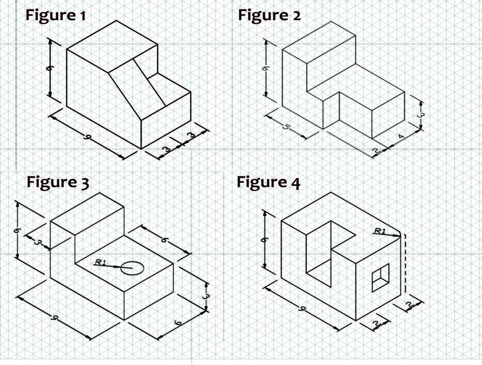
Three View Orthographic Drawing at GetDrawings Free download
Engineering Drawing Views & Basics Explained Fractory (2022)
Three View Orthographic Drawing at Explore
3 Views Of Isometric Drawing at Explore collection

How To Draw In 3D A Comprehensive Guide To 3 Point Perspective Drawing
Three View Orthographic Drawing at Explore
Three View Orthographic Drawing at Explore
Three View Orthographic Drawing at Explore
Three View Orthographic Drawing at Explore
3 Views Of Isometric Drawing at Explore collection
An Orthographic View Or Orthographic Projection Is A Way Of Representing A 3D Object In 2 Dimensions.
Web Types Of Views Used In Drawings.
Special Agent, Said The Image Captured By Doug Mills, A New York Times Photographer, Seems To Show A Bullet Streaking Past Former President Donald J.
Hidden Lines Represent Features Obstructed From View.
Related Post: