Equipment And Mechanical Drawings Are Typically Drawn By The
Equipment And Mechanical Drawings Are Typically Drawn By The - Web technical drawing, drafting or drawing, is the act and discipline of composing drawings that visually communicate how something functions or is constructed. Mechanical part drawings are crucial for manufacturing, as they guide the production process. Web mechanical part drawings are the most common type of engineering drawing. Technical drawing is essential for communicating ideas in industry and engineering. The drawing should be studied carefully before beginning any work. These drawings are essentially the blueprints or plans for manufacturing a wide array of products and structures. In this section, we’ll explore the basic principles that govern engineering drawing, including geometric shapes, lines, angles, dimensions, scale, proportion, symbols, and notations. They provide a clear visual representation of the shape, size, dimensions, materials, construction and functionality of the finished product. State the five types of information provided in the title block of an engineering drawing. The reader should attempt to visualize what is being shown on the drawing and how it will be built. Web mechanical part drawings are the most common type of engineering drawing. In learning drafting, we will approach it from the perspective of manual drafting. Web typical assembly drawings include gearbox drawings, roller drawings, guard system drawings. State the five types of information provided in the title block of an engineering drawing. General arrangement drawings, detail drawings, assembly drawings, and auxiliary views. It displays information about various mechanical systems, such as hvac (heating, ventilation, and air conditioning). It is more than simply a drawing, it is a graphical language that communicates ideas and information. Mechanical part drawings are crucial for manufacturing, as they guide the production process. The basic drawing standards and conventions are the same regardless of what design tool you use to make the drawings. They give an exact representation of the object and show all parts in their true size relation. It is more than simply a drawing, it is a graphical language that communicates ideas and information. Web mechanical part drawings are the most common type of engineering drawing. The basic drawing standards and conventions are the same regardless of what design tool you use to make the drawings. In learning drafting, we will approach it from the perspective of. General arrangement drawings, detail drawings, assembly drawings, and auxiliary views. In learning drafting, we will approach it from the perspective of manual drafting. Web the layout of most drawings is similar in that the drawing format has some standard features or components. The assembly drawing will generally include at least three orthographic views with sections as needed to clearly show. Web mechanical drawings show the mechanical systems and equipment of the project, such as hvac, plumbing, fire protection, etc. Web mechanical part drawings are the most common type of engineering drawing. Web mechanical systems drawing is a type of technical drawing that shows information about heating, ventilating, air conditioning and transportation around the building (elevators or lifts and escalator). Web. Web technical drawing, drafting or drawing, is the act and discipline of composing drawings that visually communicate how something functions or is constructed. Reading and interpreting these drawings is crucial for understanding the design intent and specifications of a product. Web typically, the ___ draws the equipment, mechanical, electrical, and plumbing plans. A common use is to specify the geometry. If the drawing is made Web these foundational concepts ensure that the drawings are accurate, consistent, and universally understood. Web in architecture, dimensions are usually linear and drawn as a line, with the dimension written in feet/inches above it. State the five types of information provided in the title block of an engineering drawing. Area where the job specifications are. They give an exact representation of the object and show all parts in their true size relation. Web typically, the ___ draws the equipment, mechanical, electrical, and plumbing plans. They provide a clear visual representation of the shape, size, dimensions, materials, construction and functionality of the finished product. Usually, a number of drawings are necessary to completely specify even a. Web mechanical drawings show the mechanical systems and equipment of the project, such as hvac, plumbing, fire protection, etc. A common use is to specify the geometry necessary for the construction of a component and is called a detail drawing. They provide a clear visual representation of the shape, size, dimensions, materials, construction and functionality of the finished product. Area. Area where the job specifications are listed; Electrical drawings show the electrical systems and components of the. Reading and interpreting these drawings is crucial for understanding the design intent and specifications of a product. The reader should attempt to visualize what is being shown on the drawing and how it will be built. A common use is to specify the. A common use is to specify the geometry necessary for the construction of a component and is called a detail drawing. State how the grid system on an engineering drawing is used to locate a piece of equipment. They give an exact representation of the object and show all parts in their true size relation. Bill of materials or material. Web in architecture, dimensions are usually linear and drawn as a line, with the dimension written in feet/inches above it. State how the grid system on an engineering drawing is used to locate a piece of equipment. If the drawing is made Usually, a number of drawings are necessary to completely specify even a simple component. Electrical drawings show the. Web an engineering drawing is a type of technical drawing that is used to convey information about an object. In this section, we’ll explore the basic principles that govern engineering drawing, including geometric shapes, lines, angles, dimensions, scale, proportion, symbols, and notations. Web engineering drawing is a specialized form of communication that uses a strict set of symbols, standards, and perspectives to depict mechanical, electrical, or structural designs. Detail drawings provide information about specific parts that make up an object, such as measurements and tolerances for bolts or screws. The drawing should be studied carefully before beginning any work. General arrangement drawings show the overall design of a machine or device and are used when there are many parts that need to be shown. Web assembly drawings show how parts fit together to form a larger object, like an engine or machine. These drawings are essentially the blueprints or plans for manufacturing a wide array of products and structures. Usually, a number of drawings are necessary to completely specify even a simple component. Web interpreting drawings requires the ability to visualize and the ability to interpret what is being drawn and written. The basic drawing standards and conventions are the same regardless of what design tool you use to make the drawings. The reader should attempt to visualize what is being shown on the drawing and how it will be built. They give an exact representation of the object and show all parts in their true size relation. A common use is to specify the geometry necessary for the construction of a component and is called a detail drawing. Web in architecture, dimensions are usually linear and drawn as a line, with the dimension written in feet/inches above it. The assembly drawing will generally include at least three orthographic views with sections as needed to clearly show all of the details and their relative positions.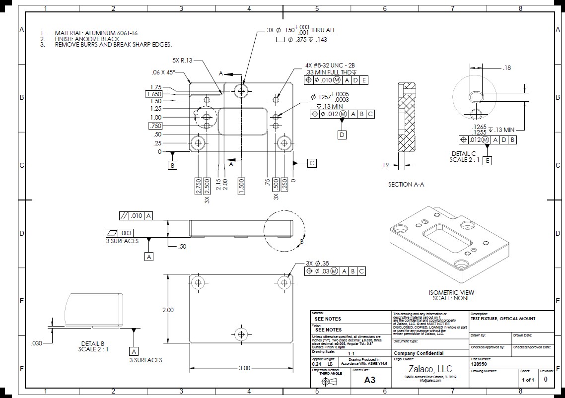
Zalaco, LLC
50+ Drawing Definition Mechanical Images basnami

How To Draw Mechanical Drawings In Autocad at How To Draw

Mechanical Drawing Mechanical engineering design, Industrial design
How to Read Mechanical Drawings Tulsa Welding School

Mechanical Drawings bartleby

detailed assembly drawing Mechanical engineering design, Mechanical
Understanding Mechanical Drawings Mechanical Drafting Course

Engineering
Technical Drawing In Mechanical Engineering
They Provide A Clear Visual Representation Of The Shape, Size, Dimensions, Materials, Construction And Functionality Of The Finished Product.
Web Mechanical Part Drawings Are The Most Common Type Of Engineering Drawing.
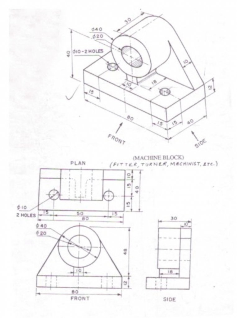
A Typical Drawing Format Will Include Some Or All Of These Features:
Mechanical Part Drawings Are Crucial For Manufacturing, As They Guide The Production Process.
Related Post: