Isometric Pipeline Drawing
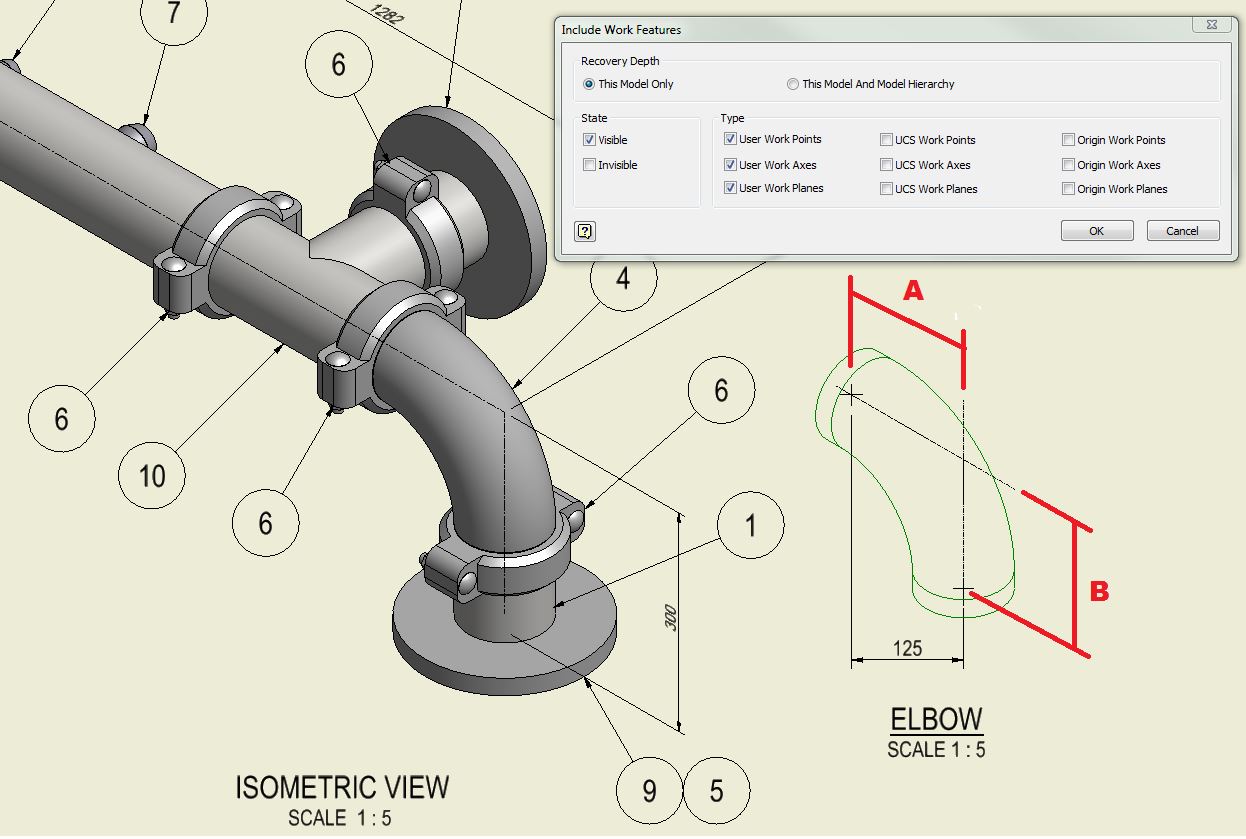
Isometric Pipeline Drawing - Web introduction to piping isometric reading; It should be noted, however, that the dimensioning in the drawings, despite the scaling down is always in proportion. Consider at some point northing of pipe’s face is n 524.196 and the pipe traveled towards the south by 10.94m then the current coordinate. Web piping isometrics drawing and fabrication management software. Web isometric is not extracted correctly for custom created pipe sizes in autocad plant 3d. The knowledge gained in this course will help you to understand all isos so that you can draw the correct information from them. Web how to read piping isometric drawing symbols. Basic piping isometric symbols : Web a piping isometric drawing is a technical drawing that depicts a pipe spool or a complete pipeline using an isometric representation. Web it is the most important deliverable of piping engineering department. Web the isometric view shows the same pipe as in the orthographic view. These tools generate the 3d representation of the piping layout, including pipe dimensions, fittings, valves, and other components. Although the pipeline is accurately dimensioned, it is deliberately not drawn to scale and therefore does not correspond exactly to a real pictorial illustration of. Web piping isometrics drawing and fabrication management software. These drawings are critical for the design, construction, and maintenance of piping systems, providing detailed information about the size, shape, and route of pipes, as well as. Web how to read piping isometric drawing symbols. Web introduction to piping isometric reading; Correct skey is not configured in isoskeyacadblockmap.xml. Web understanding piping isometric drawings: Web checking piping isometric drawings before finally releasing them to the construction team is very important. These drawings are critical for the design, construction, and maintenance of piping systems, providing detailed information about the size, shape, and route of pipes, as well as. The red lines show the pipe, the black dots are the butt welds and a, b and c are the dimensions of front to. Web piping isometric drawing software is an essential tool. Understanding the intricacies of pipeline isometric drawings, including iso standard isometric symbols, fittings, flanges, valves, and special components, is foundational for professionals in the. A comprehensive guide piping isometric drawings are essential documents in the field of mechanical engineering, particularly in industries such as petrochemicals, oil and gas, and power generation. Web easy isometric is the first pipe isometric drawing. Iso pipes are typically drawn using specialized software such as avicad which supports isometric drawings. These drawings are critical for the design, construction, and maintenance of piping systems, providing detailed information about the size, shape, and route of pipes, as well as. Web anatomy of a piping isometric drawing. These tools generate the 3d representation of the piping layout, including. Web checking piping isometric drawings before finally releasing them to the construction team is very important. Consider at some point northing of pipe’s face is n 524.196 and the pipe traveled towards the south by 10.94m then the current coordinate. Web it is the most important deliverable of piping engineering department. Web this course will make you a piping isometric. These drawings are critical for the design, construction, and maintenance of piping systems, providing detailed information about the size, shape, and route of pipes, as well as. Basic piping isometric symbols : The red lines show the pipe, the black dots are the butt welds and a, b and c are the dimensions of front to. Web creating a piping. Although the pipeline is accurately dimensioned, it is deliberately not drawn to scale and therefore does not correspond exactly to a real pictorial illustration of. As you can see, this drawing is very simple and quick to implement. Web understanding piping isometric drawings: Web how to read piping isometric drawing symbols. The knowledge gained in this course will help you. Web isometric pipe drawing plays a crucial role in engineering, construction, and design, providing a clear and accurate representation of complex piping systems. Anatomy of a piping isometric drawing; It’s crucial to read and understand these drawings for professionals in various industries like oil and gas and manufacturing. It should be noted, however, that the dimensioning in the drawings, despite. Web checking piping isometric drawings before finally releasing them to the construction team is very important. It minimizes errors and improves quality. Basic piping isometric symbols : The knowledge gained in this course will help you to understand all isos so that you can draw the correct information from them. Piping fabrication work is based on isometric drawings. These drawings have become an indispensable tool for representing complex pipeline structures. Web this course will make you a piping isometric expert, and you will know how to read, interpret and successfully understand all of those many lines and piping symbols. Piping fabrication work is based on isometric drawings. These tools generate the 3d representation of the piping layout, including. Iso pipes are typically drawn using specialized software such as avicad which supports isometric drawings. Web piping isometrics drawing and fabrication management software. Web checking piping isometric drawings before finally releasing them to the construction team is very important. Rhea, in pipe drafting and design (fourth edition), 2022 abstract. Web the isometric view shows the same pipe as in the. Automated bill of materials no more tedious material tracking when creating a pipe isometric drawing. Start with idf or pcf files, installation drawings, or draw spools directly. Web checking piping isometric drawings before finally releasing them to the construction team is very important. Consider at some point northing of pipe’s face is n 524.196 and the pipe traveled towards the south by 10.94m then the current coordinate. An extensive discussion of the need for, and development of, piping isometric drawings is provided. Piping isometric drawing consists of three sections. These tools generate the 3d representation of the piping layout, including pipe dimensions, fittings, valves, and other components. Basic isometric symbols 15 topics. Create isometric drawings in minutes: Web this course will make you a piping isometric expert, and you will know how to read, interpret and successfully understand all of those many lines and piping symbols. The knowledge gained in this course will help you to understand all isos so that you can draw the correct information from them. Isometric drawings are typically used to show the details of a piping system, such as the size and type of piping, the direction of flow of the fluids, and the location of valves, pumps, and other equipment nozzles. Correct type and skey is not configured for pipe in catalog editor. It’s crucial to read and understand these drawings for professionals in various industries like oil and gas and manufacturing. Open the autocad plant 3d project drawing file. Piping fabrication work is based on isometric drawings.
How to read piping isometric drawing, Pipe fitter training, Watch the
Piping Isometric Drawings Autodesk Community

How to read piping isometric drawing pdf fleetlio
Pipeline Isometric Drawings Explained NDT Techniques & Interpretation
Isometric Pipe Line CAD Drawing Free Download DWG File Cadbull

Piping Design Basics Piping Isometric Drawings Piping Isometrics

Sample isometric drawing for piping klowebcam
Drawings of ISOMETRIC PIPING DIAGRAMS retgas
Isometric Pipe Drawing at GetDrawings Free download

How to read piping Isometric drawing YouTube
A Comprehensive Guide Piping Isometric Drawings Are Essential Documents In The Field Of Mechanical Engineering, Particularly In Industries Such As Petrochemicals, Oil And Gas, And Power Generation.
Anatomy Of A Piping Isometric Drawing;
It Should Be Noted, However, That The Dimensioning In The Drawings, Despite The Scaling Down Is Always In Proportion.
These Drawings Essentially Provide A Detailed Visual Representation Of Complex Piping Systems.
Related Post: